Introduction: Understanding TIM Gap Fillers—Why Thickness Matters
When electronic devices heat up, their performance and lifetime are at stake. That’s why Thermal Interface Materials (TIMs)—including gap fillers—are so essential. But, in real-world assembly, one question arises: How does the thickness of a TIM gap filler impact efficiency? This article unlocks the relationship between TIM gap filler thickness and heat transfer efficiency, with insights into material choices, installation challenges, reliability, and the hidden trade-offs every engineer, designer, or manufacturer should know.
The Science Behind TIM Gap Fillers: Basic Principles

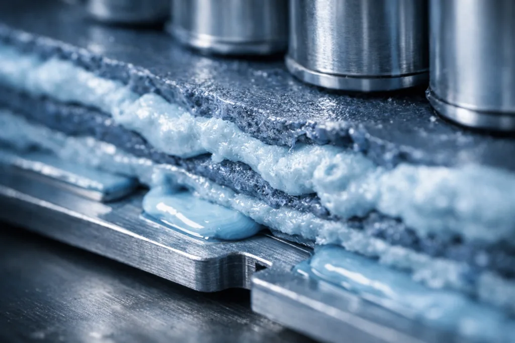
Thermal interface materials act as bridges between heat-generating components and heat sinks. Their main job is to reduce the air gaps caused by surface roughness, which would otherwise trap heat. The goal? Achieve more efficient heat transfer by minimizing thermal resistance. The gap filler, a soft, compressible type of TIM, adapts to uneven surfaces, making it popular for automotive, power electronics, and telecommunications.
The Relationship Between TIM Thickness and Efficiency
Many engineers wonder if using a thicker gap filler will solve heat issues once and for all. In practice, the answer hinges on a delicate balance. Thicker TIMs can compensate for large surface unevenness, but excessive thickness often lowers thermal conductivity and increases overall thermal resistance. The thinner the TIM (while still filling all microgaps), the better the efficiency—until mechanical tolerances or safety standards dictate otherwise.
Thermal Conductivity vs. Thickness: Key Equations Simplified
Heat transfer follows Fourier’s law: Q = (k × A × ΔT) / d. Here, Q is the amount of heat transferred, k is thermal conductivity, A is area, ΔT is temperature difference, and d is TIM thickness. Increasing TIM thickness (d) tends to decrease the rate of heat transfer—unless offset by increasing k (better TIM formulation). But there’s always a trade-off between flexibility, compressibility, and core conductivity.
Common TIM Gap Filler Materials and Their Thickness Ranges
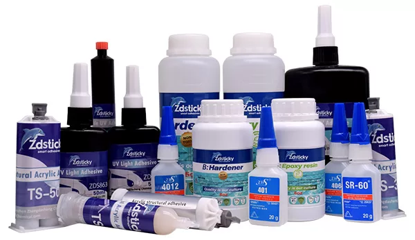
Gap fillers can be made from silicone, polyurethane, or acrylic matrices, often loaded with thermally conductive particles like ceramics or graphite. These materials enable a large range of thickness—typically 0.2 mm up to 5.0 mm, depending on the gap size in your design. For more on how these families compare, see our guide on epoxy vs silicone vs polyurethane adhesives.
Industry Standards and Regulatory Benchmarks
Many devices—especially automotive, EV, and battery pack assemblies—follow UL94 flame retardancy standards, RoHS requirements, and OEM-specific thermal reliability or outgassing protocols. They may also specify maximum allowed TIM thicknesses or minimum conductivity levels based on application risk. Staying compliant is critical for mass market electronics and regulated sectors.
How Thickness Impacts Reliability & Performance in Real Assemblies
In practice, thicker TIM gap fillers often provide better surface contact, reducing the risk of air entrapment—but at a cost. Thicker materials can suffer from greater “thermal resistance stacking,” mechanical instability, and pump-out risk under vibration or thermal cycling. Practices such as pre-compression testing, fixture pressure checks, and selecting the right thermal adhesive can help validate your design choices.
Design Trade-offs: Thicker vs. Thinner TIM Gap Fillers
Choosing the optimum thickness is rarely about going thinner or thicker without context. Thicker TIMs can bridge big gaps and improve assembly tolerances, but too much thickness reduces heat flow. Thinner TIMs transfer heat better but demand more precise, even surfaces. Often, a mid-range thickness is selected for reliability and ease of application.
Compression and Conformability: The Hidden Efficiency Factor
Effective use of gap fillers depends not just on their listed thickness, but on their ability to compress and follow surface contours. For instance, a 2.0 mm thick gap filler that compresses by 50% can outperform a rigid 1.0 mm pad in poor contact conditions. This behavior highlights the value of detailed, realistic assembly simulations and quality control on the line.
Effect of Thermal Cycling and Stress on TIM Efficiency
Repeated heating and cooling cycles can expand, contract, and sometimes even “pump out” softer TIMs from their designed location, especially when used in thicker layers. Materials with optimized viscoelasticity and proper surface adhesion can help maintain consistent performance over hundreds or thousands of cycles.
Case Study: Applying TIM Thickness in Automotive Battery Packs
Automotive battery modules demand both electrical insulation and maximum heat dissipation. Here, the push for thin, conformal gap fillers (0.5–1.5mm) enables best-in-class heat transfer. Design teams use pressure mapping and finite element analysis (FEA) to model the effect of various thicknesses in real load and vibration scenarios—avoiding overspecification that can reduce efficiency or compromise safety.
Case Study: Consumer Electronics & Miniaturized Devices
Smartphones, tablets, and wearables use ultra-thin gap fillers (<1mm) to maximize heat extraction in very tight spaces. Thicker pads can’t physically fit, and even small increases in thickness can lead to overheating or swelling. Thermal simulation, side-by-side thermal imaging, and physical teardown confirm the smallest workable thickness for every design iteration.
Comparing Gap Filler Performance: Table of Thermal Resistance
| Material Type | Typical Thickness (mm) | Thermal Conductivity (W/mK) | Total Thermal Resistance (K·cm²/W) |
|---|---|---|---|
| Silicone gap filler | 1.0 | 2.0 | 0.5 |
| Polyurethane pad | 2.0 | 1.2 | 1.7 |
| Acrylic gel | 0.5 | 1.5 | 0.3 |
| Ceramic-filled silicone | 3.0 | 4.0 | 2.3 |
*Lower resistance is better for heat flow. Notice how thicker, lower-conductivity pads boost resistance even if the material has better physical coverage.*
Thermal Management in Harsh Environments: Special Considerations
Applications like outdoor telecom, EV charging stations, or satellites face wide temperature swings. Here, TIM gap fillers must hold their form and function over years, and managing thickness helps limit the risk of slow degradation. Water resistance, salt spray, and UV stability further complicate material and thickness choices—referenced in waterproof and outdoor adhesive solutions.
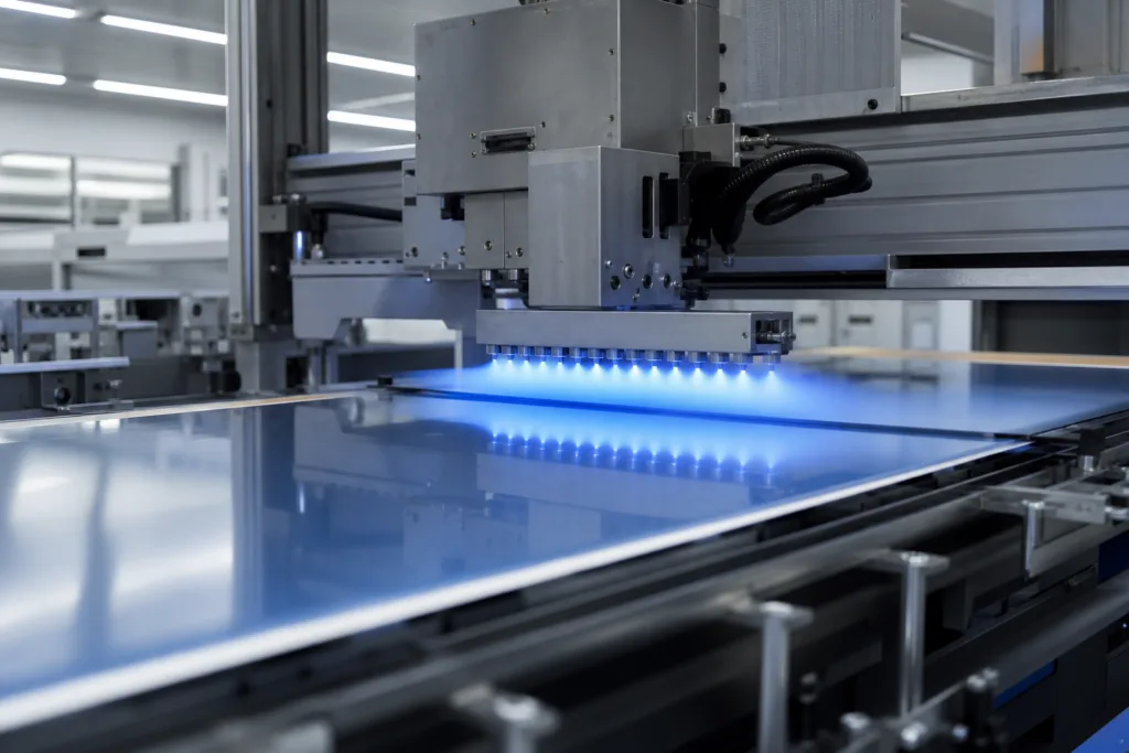
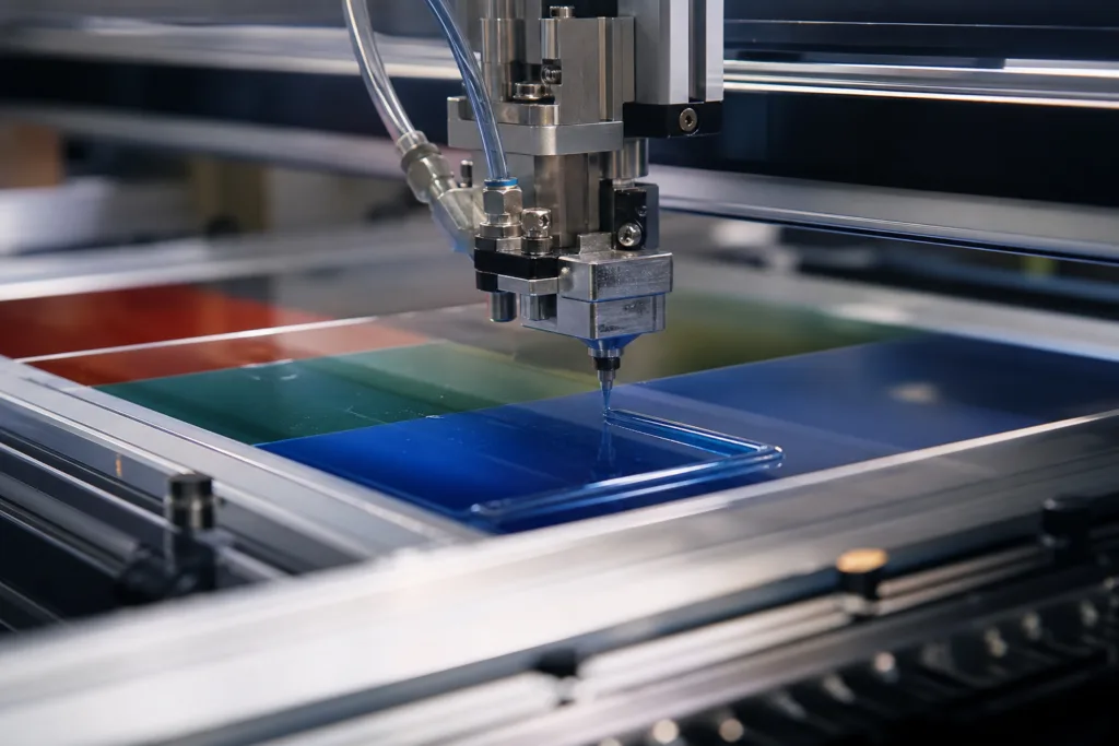
Assembly-Line Realities: Gap Filler Thickness & Production Tolerance
From an assembly-line viewpoint at ZDS Adhesive, an industrial adhesive manufacturer, control over TIM thickness is a key process variable. Too thin, and air gaps slip through. Too thick, and the end product may not close, or sheds heat inefficiently. Verifiable, repeatable application—by automated dispensing or pad placement—trims time wastage and improves field reliability. Final thickness checks are often as important as conductivity ratings themselves when validating production lines for automotive, industrial, and consumer sectors.
Testing TIM Gap Fillers: Best Practices & Lab Methods
Lab testing of TIM gap fillers covers not just thermal conductivity, but also long-term stability, reworkability, and compression set. Lap shear, peel, and thermal cycling—all at various thicknesses—help teams pinpoint the limits before moving into production. In-process sample pulls and coupon testing (post-cure) close the reliability loop.
Trends in Gap Filler Materials: 2026 and Beyond
The latest generation of TIM gap fillers features hybrid formulations—combining high-conductivity fillers with flexible, low-outgassing binders. Markets demand thinner, more stable, and safer gap fillers. Sustainable alternatives and rapid-curing systems gain ground, offering assemblies with tighter tolerances and higher throughput in automated lines.
Choosing the Right TIM Gap Filler: A Step-by-Step Guide
- Map your thermal design—identify hot spots and required performance
- Assess maximum allowable thickness (assembly, safety, or enclosure limits)
- Select material based on conductivity, compression, and aging behavior
- Prototype with two or more thickness grades and test for real-world fit and function
- Iterate, measure, and validate through field and lab trials
TIM (Thermal Interface Materials) Gap Fillers: Thickness vs. Efficiency
There is no one-size-fits-all answer when it comes to TIM gap filler thickness versus efficiency. Every assembly demands a custom balance—enough material to reliably fill any voids, but not so much that you create a long, resistive thermal path. Key performance metrics will depend on your device’s operating environment, manufacturing realities, and failure/risk tolerance. Above all, careful selection, validation, and routine quality control are non-negotiable for next-generation electronics and power systems.
Frequently Asked Questions
How does TIM thickness affect thermal performance?
Thicker TIMs can help fill large gaps and improve contact, but added thickness increases thermal resistance, slowing heat flow. Thinner TIMs transfer heat more efficiently up to the point where they still fill all voids without air gaps.
Can you always improve performance by using a higher thermal conductivity material?
Improving thermal conductivity helps, but very thick TIMs may still have a high overall resistance. The best results usually come from balancing a good material and the thinnest workable layer.
What are the risks of using overly thick gap fillers?
Potential risks include increased pump-out, loss of mechanical integrity, excess deformation, and greater chances of thermal cycling failures, especially in high-vibration or long-life assemblies.
Are silicone-based gap fillers better than other types?
Silicone gap fillers are widely used due to flexibility and stability, but polyurethane and acrylic options can also be a better fit, depending on temperature requirements and chemical compatibility.
How do you determine the ideal TIM thickness for my application?
Ideal thickness comes from a combination of device surface flatness, required thermal resistance, assembly tolerances, and prototype testing under real load.
Do industry standards define maximum TIM thickness?
Some sectors, such as automotive and EV battery assembly, may set limits for safety and performance. Otherwise, industry benchmarks focus more on thermal resistance thresholds than thickness alone.
Related Reading
- Silicone or Polyurethane? Decoding Potting Choices for Battery Modules
- How Structural vs. Thermal Adhesives Drive CTP Battery Innovation
- Outdoor & Waterproof Adhesives: Creating Durable Bonds in Extreme Environments
- Unlocking Maximum Adhesion: The Best Industrial Adhesives for Metal Bonding
- Marine Adhesive Innovation Forecast: What Experts Expect by 2026