Introduction to Low Dielectric Constant Coatings for 5G/RF PCBs
When it comes to high-frequency electronic design in 2026, Low Dielectric Constant Coatings for 5G/RF PCBs have become a linchpin for performance and reliability. These specialized coatings play a pivotal role in minimizing signal loss, bolstering signal integrity, and enabling robust connections required for the latest 5G and RF applications. Understanding why coating materials with low dielectric constants matter can help engineers and designers unlock peak PCB performance while avoiding costly failures.
Understanding Dielectric Constant: Why It Matters

The dielectric constant (also called relative permittivity) is a key property that affects how electromagnetic signals travel through a material. In PCB coatings, a low dielectric constant means less energy is stored and less signal distortion occurs, making communication lines clearer and faster. This is especially critical for 5G and RF circuits where frequencies can easily exceed several gigahertz (GHz).
The Evolution of 5G/RF PCB Demands
With the rise of 5G wireless technology, RF systems are expected to handle ever-higher data rates and ultra-low latency requirements. As signals travel faster and board densities increase, traditional PCB coatings with higher dielectric properties can lead to signal reflection, crosstalk, and attenuation. To keep up, manufacturers favor low dielectric coatings that maintain clean, reliable signal pathways.
How Low Dielectric Constant Influences Signal Integrity
A lower dielectric constant directly translates to less capacitance between conductors. This reduces unwanted coupling and prevents the delays and distortions that compromise data streams. PCB designers see measurable improvements in eye diagrams, time domain reflectometry (TDR) measurements, and transmission line performance when low Dk materials are used as coatings or substrates.
Key Benefits of Low Dielectric Constant Coatings
- Improved Signal Integrity: Minimize bit errors and jitter in high-speed data lanes.
- Reduced Signal Loss: Limit attenuation for both differential and single-ended signals, keeping RF performance optimal.
- Better Thermal Management: Low Dk coatings often also provide low dissipation factor, meaning less heat generation from dielectric loss.
- Higher Frequency Bandwidth: Supports millimeter wave (mmWave) and other advanced 5G requirements with lower insertion loss.
Materials Used in Low Dielectric Constant Coatings
Modern 5G/RF PCB coatings leverage innovative chemistries to achieve low dielectric constants while remaining processable, reliable, and cost-effective. Some common materials include:
- Fluoropolymers (e.g., PTFE, FEP): Among the lowest Dk (typically <2.2), great for microwave and high-frequency PCBs.
- Silicones and Polyimides: Low Dk, plus flexibility and temperature resistance—often used for space-constrained modules.
- Epoxy/Silicone Hybrids: Tuned for low Dk and industrial durability; they are also found as epoxy adhesives for PCB assembly.
- Ceramic-Filled Polymers: Balance high-performance dielectric and mechanical strength, useful for harsh environments.
How Coatings Are Applied: Process Insights
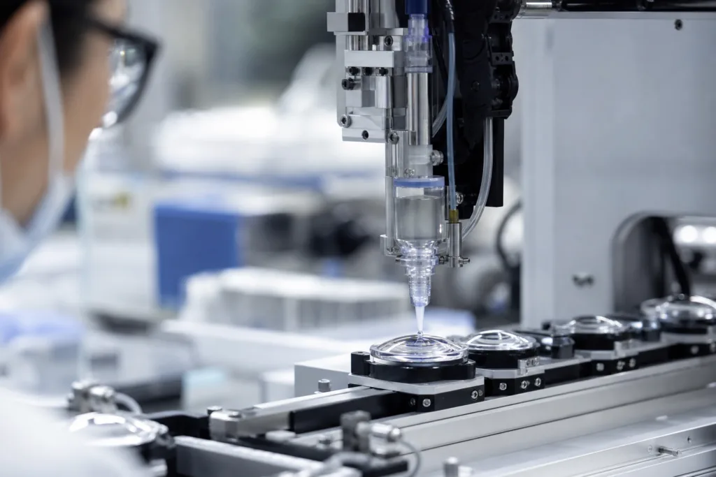
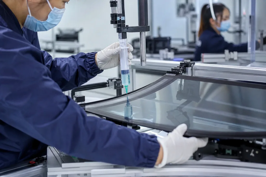
Low dielectric coatings are typically applied using spray, dip, or selective coating techniques. Consistent thickness and uniformity are vital—variance can impact layer capacitance and thus the expected electrical performance. In production, using UV-curable maskants can help streamline complex coating patterns and reduce downtime.
Applications in 5G and RF Devices
These coatings are critical in:
- 5G mmWave antenna boards
- RF power amplifiers
- Low-noise receivers and front-end modules
- Automotive radar (ADAS) and V2X units
- Advanced smartphones and wireless IOT hubs
All rely on coatings that won’t add parasitic effects or jeopardize RF matching and EMI shielding. Selecting the right low dielectric material helps maintain transmission line control and minimizes failures under demanding use cycles.
Thermal Management: A Hidden Benefit
Beyond electrical performance, low dielectric coatings typically offer lower dissipation factors, which translate into less self-heating under high-frequency use. This reduces hot spots and improves PCB lifespan. Some hybrid coatings improve both thermal stability and electrical insulation, key factors in dense 5G base station or automotive RF modules.
Performance Testing: How Low Dielectric Coatings Are Evaluated
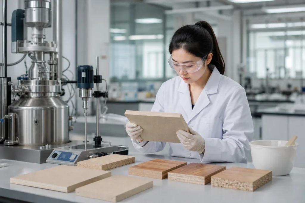
Verifying the dielectric properties isn’t just a datasheet check. Labs commonly use split post dielectric resonators, TDR, and S-parameter analyses to confirm coating effectiveness at target frequencies. For mission-critical 5G/RF applications, tests also cover adhesion, thermal cycling, humidity exposure, and chemical resistance, mimicking real-use failure modes. From experience at ZDS Adhesive, an industrial adhesive manufacturer, coating qualification at the prototype stage often includes both performance mapping and rework evaluation to ensure robust long-term yields.
Common Challenges in Coating Implementation
While benefits are clear, implementing low dielectric coatings comes with practical hurdles:
- Material Compatibility: Coatings must bond reliably to copper traces, solder masks, and substrates; poor adhesion can cause delamination.
- Processing Windows: Some ultra-low Dk polymers are sensitive to cure schedules or environmental humidity, impacting reflow or repair cycles.
- Cost and Sourcing: Not all low Dk materials are available worldwide, and cost can climb rapidly for exotic chemistries.
Engineers often balance these against performance goals and production realities.

Solutions to Common Implementation Issues
Successful programs mitigate challenges with a combination of careful selection and smart process controls:
- Use surface preparation techniques like plasma or corona to boost adhesion.
- Verify that application method (spray, dip, robot, selective) matches PCB layout and tolerances.
- When dealing with complex shapes, consider modular masking using UV systems to decrease overspray and wasted material.
- For tough operating environments, ceramic-filled or hybrid coatings may offer the ideal balance of Dk, adhesion, and chemical durability.
For more about surface preparation and its impact on adhesion, see this in-depth guide on surface preparation.
Comparison of Low Dielectric Coating Materials
| Material | Dielectric Constant (Dk) | Main Strengths | Main Limitations |
|---|---|---|---|
| Fluoropolymers | ~2.1 | Lowest Dk, most inert, high-temp stability | High cost, difficult to process |
| Silicones | ~2.8–3.2 | Flexible, resists moisture, easy process | Lower mechanical strength |
| Epoxy hybrids | ~3.0–3.6 | Good toughness, reworkable in some systems | Medium Dk, may yellow under UV |
| Ceramic-filled | ~3.2–4.0 | Improved chemical & thermal durability | Higher Dk than pure fluoropolymers |
Sustainability and Environmental Trends
The move toward green electronics is impacting the selection of coating chemistries. Some manufacturers are phasing out materials with high toxicity, volatile organic compounds (VOCs), or halogens. For a closer look at these trends, check out the article on low-halogen epoxies in green electronics.
Real-World Application: Case Study Snapshots
- A telecom firm upgraded their base station PCBs, replacing traditional epoxy coatings with a low Dk fluoropolymer for their mmWave modules, reporting a 12% reduction in signal loss and improved range.
- An automotive radar supplier standardized on ceramic-filled coatings to handle under-hood heat cycling, which reduced delamination returns by 20% over previous systems.
Failure Modes and How to Prevent Them
Typical failures include “orange peel” defects and moisture ingress, which both degrade dielectric performance and introduce leakage. Detailed process controls and correct coating selection are critical. For step-by-step ways to avoid coating defects, see the post on eliminating orange peel in conformal coatings.
Emerging Trends: Nano-Fillers and Advanced Chemistries
Research into nano-fillers (like nanosilica or boron nitride) has enabled the fine-tuning of dielectric and thermal properties. These fillers distribute evenly within coatings, lowering Dk without sacrificing toughness. Want to know more about advanced fillers? Read about nano-fillers in thermal conductive epoxies.
Quality Assurance and Longevity
Ensuring reliable coating performance over a product’s life means thorough QA programs with periodic electrical, visual, and weathering tests. Many assembly lines automate thickness measurement and adhesion pull tests for each lot. Detailed records back up long-term warranties—an approach ZDS Adhesive’s application engineers have seen pay off in highly regulated markets like automotive and aerospace.
Low Dielectric Constant Coatings for 5G/RF PCBs

To sum up, Low Dielectric Constant Coatings for 5G/RF PCBs are not just a piece of technical jargon—they’re a must-have for engineers aiming for high-frequency reliability and future-ready designs.
Frequently Asked Questions
What exactly is a low dielectric constant, and why is it crucial for 5G/RF PCBs?
A low dielectric constant means the material stores less electrical energy, reducing signal loss and distortion—vital for fast, clean data transmission in 5G and RF assembly.
How are low dielectric coatings different from regular conformal coatings?
Low dielectric coatings are optimized for electrical properties at high frequencies, whereas regular conformal coatings mainly protect against moisture and dust without tailoring signal performance.
What are common materials for low Dk coatings?
Popular options include fluoropolymers, silicones, polyimides, and some epoxy hybrids—all chosen for their ability to preserve signal speed and minimize interference.
Are low dielectric coatings harder to process in manufacturing?
Some, like pure fluoropolymers, can require special equipment and processing care, but many new hybrid coatings balance performance and standard process compatibility.
How can engineers prevent coating failures in high-frequency boards?
Thorough surface prep, controlled application thickness, and regular quality checks are key—along with picking chemistries suited for the board and environment.
Is there a tradeoff between electrical performance and durability?
There can be. Selecting the right formulation with both low Dk and good mechanical strength—or using hybrid/cermic-filled systems—helps minimize tradeoffs in demanding settings.
Related Reading
- Why Dielectric Strength is Key for High-Voltage Battery Safety
- Conformal Coating vs. Potting Compound: Which PCB Protection is Best?
- Thermal Control Hacks for Large Epoxy Castings
- Mastering Epoxy Project Durability with Glass Transition Temperature
- Top 10 Factors When Bonding for EV Battery Cooling Plates