Introduction to Capillary Underfill Process for Flip-Chip Packaging
The capillary underfill process for flip-chip packaging is a fundamental technique in modern semiconductor assembly. When manufacturing advanced microelectronic devices, creating reliable electrical and mechanical connections is crucial. Flip-chip packaging enables direct connection of a semiconductor die to the substrate, but it comes with significant mechanical and thermal demands. The capillary underfill process answers this challenge by distributing a special liquid adhesive under the chip. This process protects solder joints and enhances the longevity of advanced electronic products.
Why Flip-Chip Packaging Needs Capillary Underfill
Flip-chip packaging offers higher performance and lower inductance compared to traditional wire bonding. However, the solder bumps—tiny metallic spheres connecting the chip to the board—are prone to mechanical stress and thermal cycling damage. Capillary underfill compensates by filling gaps under the chip, protecting these critical joints.
Mechanics of Capillary Flow in Underfill
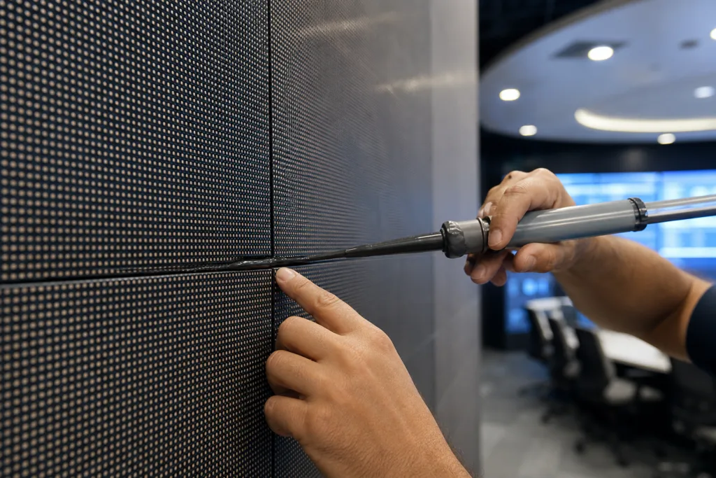
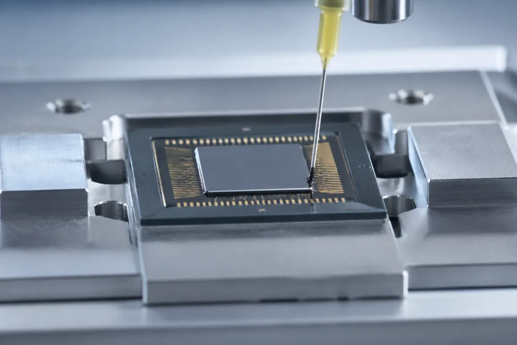
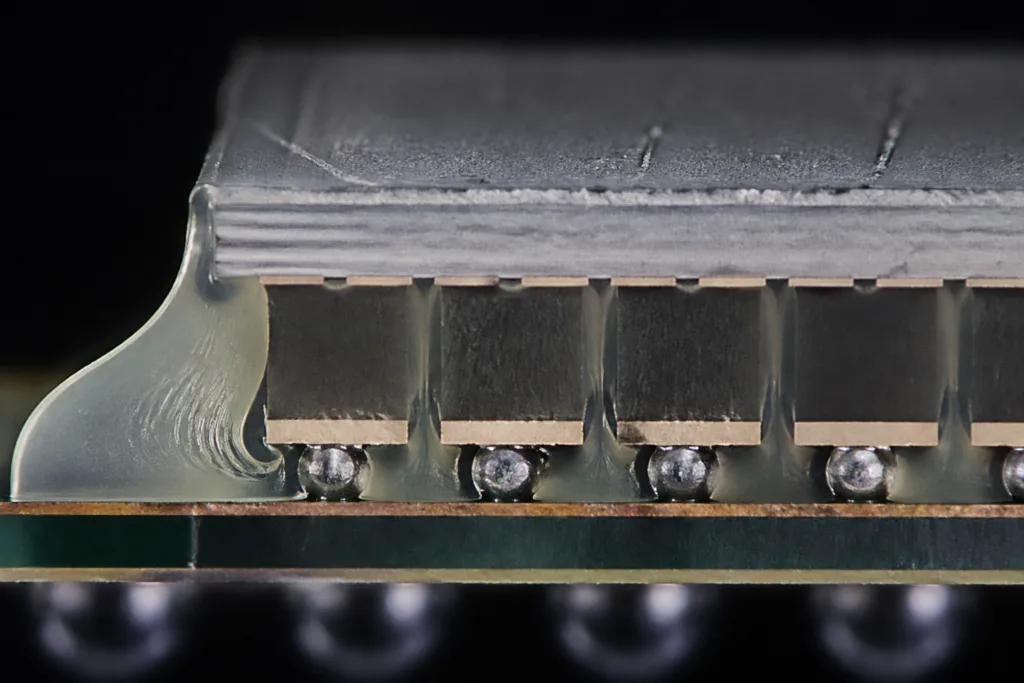
The process begins after the chip is placed and soldered onto the substrate. A low-viscosity underfill material is dispensed at one or more edges of the die. Driven by capillary action, the liquid moves rapidly beneath the chip, wetting the bumps and filling voids. The mechanics rely on surface tension, substrate wetting characteristics, and material viscosity. Surface energy differences between the board and the solder bumps determine how smoothly the underfill spreads. If designed well, the flow is even and void-free; otherwise, air can be trapped, leading to failures.
Key Factors Affecting Capillary Flow
- Material viscosity: Lower viscosity speeds up flow but may risk air entrapment.
- Surface energy: Good wetting improves underfill spread.
- Dispense time and temperature: Higher temperatures lower viscosity and speed up flow, but too much heat may cause solder reflow or hardening.
Critical Importance of Void-Free Filling
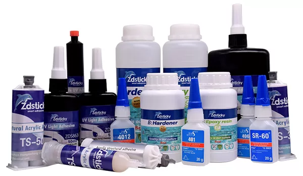
Avoiding voids during underfilling is essential to ensure every solder bump is surrounded by underfill. Voids can lead to mechanical failure, especially during temperature cycling. In high-reliability sectors like automotive and aerospace, even small voids can mean early failure. ZDS Adhesive, an industrial adhesive manufacturer, notes that precise control over dispensing speed, ambient temperature, and material rheology prevents most void-related problems in real assembly conditions.
Properties of Capillary Underfill Materials
Underfill materials are typically epoxy-based and formulated for low viscosity, rapid flow, and robust mechanical properties after cure. Important properties include:
- Low viscosity (to speed capillary flow)
- Controlled working time (so flow completes before initial gelation or cure)
- High adhesion (to both die and substrate)
- Excellent thermal cycling resistance
- Minimal shrinkage during cure
The balance between fast flow and sufficient working time is calibrated for production speeds and reliability.
Role of Surface Tension in the Capillary Process
Surface tension is a central concept in the capillary underfill process. It describes the cohesion between underfill molecules at the interface, enabling the liquid to “pull” itself beneath the chip against gravity. Effective control of surface tension and substrate wetting ensures the adhesive fills all available space and contacts every solder bump without trapping air. Surface modification of substrates—such as plasma or corona treatment—may enhance this effect and is often paired with cleaning protocols for optimal results.
Material Advancements for Modern Flip-Chip Packaging
In 2026, the range of underfill formulations has advanced to address the demand for thinner chips, smaller gaps, and higher power densities. New materials, like nano-reinforced epoxies and hybrid organic-inorganic blends, provide improved toughness and lower coefficient of thermal expansion (CTE) mismatch. For harsh environments, silicone or polyurethane-modified systems may be used, gaining insights from polyurethane moisture curing mechanisms to fine-tune assembly properties.
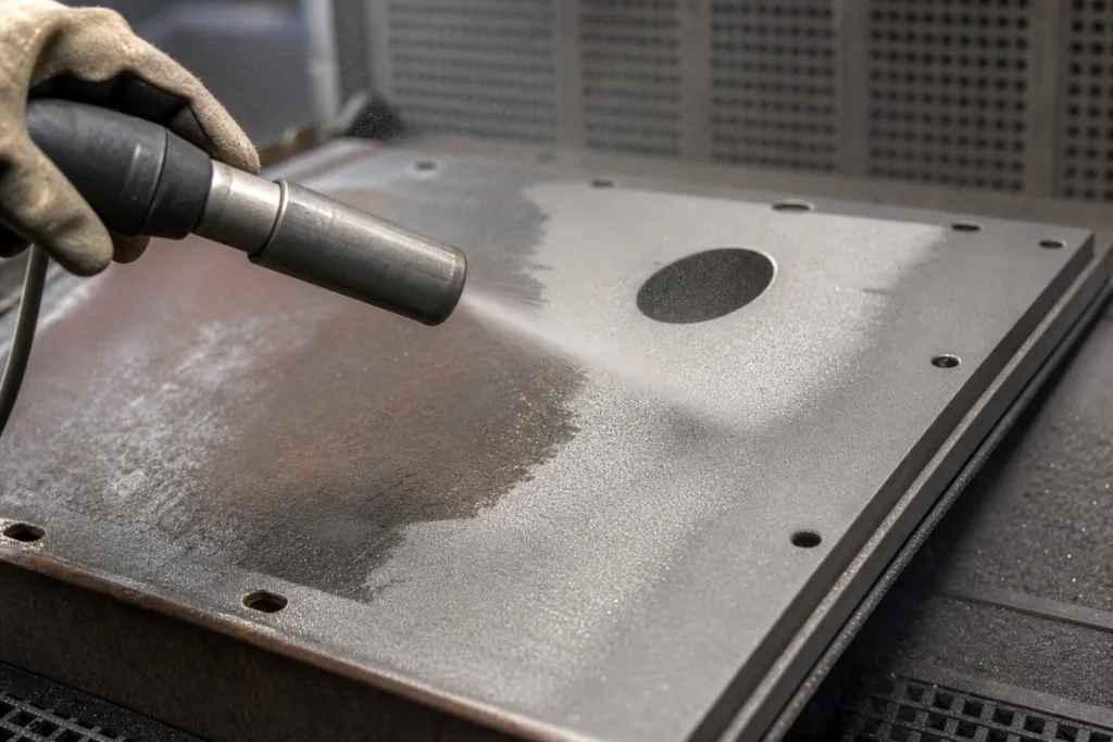
How Surface Preparation Impacts Underfilling
Surface treatment is key to consistent underfill results. Even minor contamination—such as oils from handling or residues from PCB manufacturing—can block wetting and produce voids. Simple steps like pre-assembly plasma treatment, solvent wiping, or implementation of low-stress encapsulant guidelines can dramatically boost reliability and bonding quality.
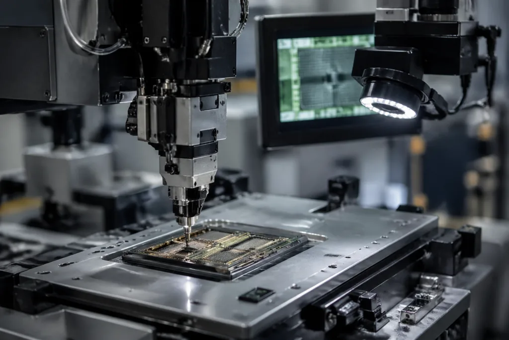
Process Steps for Capillary Underfill in Flip-Chip
- Die attach and solder reflow: The chip is soldered to the substrate under controlled conditions.
- Inspection and cleaning: Any flux residue is removed.
- Preheating (optional): Underfill flow rates increase with moderate substrate heating.
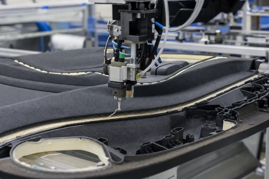
- Dispensing: Material is applied along one or more die edges.
- Capillary flow: The underfill advances beneath the chip until the gap is completely filled.
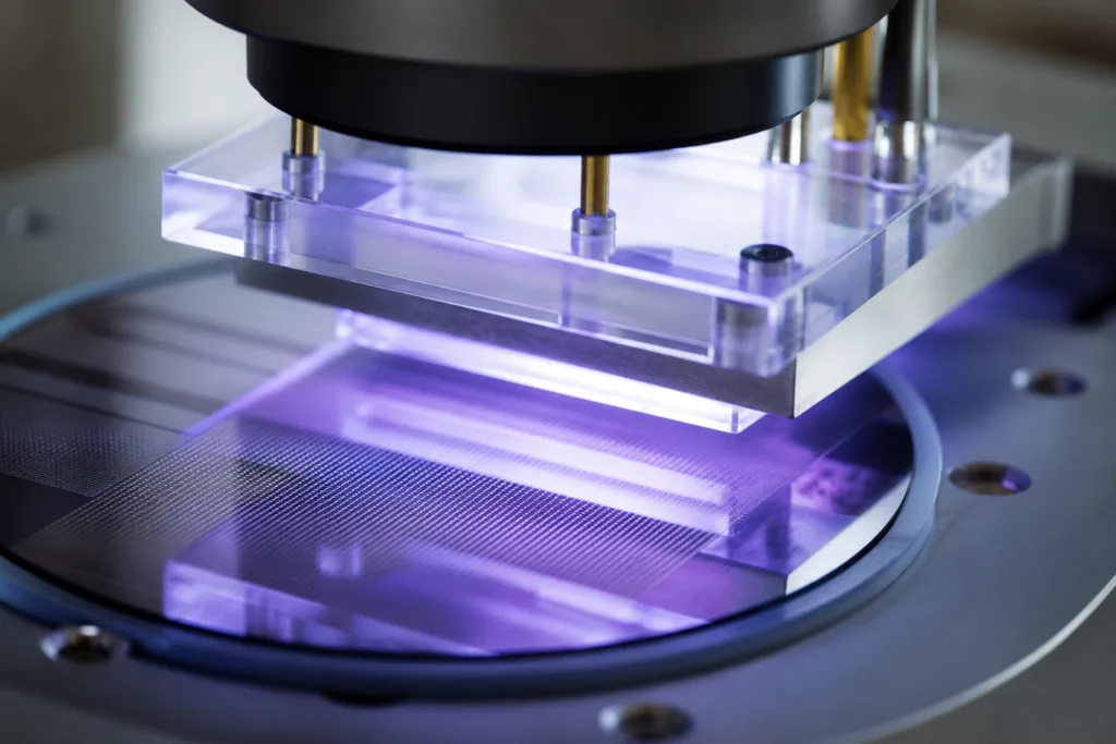
- Final cure: Heat or UV energy completes the curing, forming a tough, protective bond.
Common Challenges in Capillary Underfill for Flip-Chip Packaging
Even with advanced materials and equipment, several practical challenges remain:
- Air entrapment: Fast-moving underfill can trap air, causing voids around solder joints.
- Incomplete fill: High viscosity, improper surface energy, or insufficient dispense volume can result in gaps.
- Overflow and bleed-out: Excess underfill may spill out onto the top of the die or board, which can contaminate adjacent components.
Solder Joint Reliability and Underfill
Solder joints bear the brunt of mechanical and thermal stress. Without proper underfill, temperature changes cause expansion/contraction cycles that fatigue the joints. The adhesive improves stress distribution, reduces crack propagation, and minimizes movement. Long-term temperature/humidity cycling is routinely used in testing, with standards requiring zero solder fatigue or interfacial separation after hundreds to thousands of cycles. Learn more about reliability improvement techniques in die attach adhesives for conductivity and heat management.
Thermal Cycling Effects and Material Choices
Thermal cycling—repeated heating and cooling—can degrade both solder joints and underfill. The best adhesives feature a closely matched CTE to the substrate and chip, so that stress remains minimal during temperature swings. Additives, fillers, and hybrid resin systems help tailor this property for mission-critical designs like those in EVs or aerospace electronics.
Visual Guide: Steps in Underfill Application
| Step | Description |
|---|---|
| 1. Die Attach | Chip soldered to board, forming bumps |
| 2. Clean & Inspect | Remove flux, check for defects |
| 3. Dispense Underfill | Apply at die edge |
| 4. Capillary Flow | Underfill self-wicks under chip |
| 5. Cure | Heat or UV hardens adhesive |
| 6. Final Inspect | Check for voids/overflow |
Optimizing Capillary Underfill Parameters
Consistent production quality depends on fine-tuning variables:
- Dispense amount and location
- Substrate preheating (to promote flow)
- Material viscosity (at process temperature)
- Cure profile (temperature, time)
By monitoring these, manufacturers avoid costly rework and maximize throughput.
Advancements in Capillary Underfill Technologies (2026)
Increasing miniaturization has sparked breakthroughs in both materials and dispensing systems. Automated vision-guided dispensing heats only selected circuit regions, speeding up flow in challenging layouts. Pre-applied (No-Flow) underfills, jet dispensing, and fast-cure chemistries dramatically cut production time, all while supporting void-free filling.
Environmental and Failure Testing Protocols
After underfill, products undergo harsh environmental tests:
- Thermal cycling: -55°C to 125°C, often 500–2000 cycles
- Humidity aging: 85°C/85% RH for 1000+ hours
- Mechanical shock and vibration
Assemblies pass only if no cracks, solder fatigue, or delamination is observed. The tests are referenced by stringent IPC and JEDEC standards.
Process Stability and Real-World Assembly Insights
From an application engineer’s perspective, small changes—like adjusting substrate temperature by 10°C or switching underfill lots—can greatly impact flow time and reliability outcomes. In practice, test runs and validation are performed before full production. Understanding the types and pros & cons of silicone adhesives helps inform stable and repeatable workflows.
Smart Factory Solutions for Quality Control
Machine vision, inline X-ray inspection, and automated dispense monitoring have become standard in advanced flip-chip lines. Production data allows prediction and correction of anomalies in real time, improving yields and reducing defects.
Future Directions: Miniaturization and Heterogeneous Integration
As the industry moves to 2.5D and 3D integration, underfill technology continues to evolve. Narrow gaps, new substrate materials, and more complex interconnects require adaptive underfill solutions—sometimes combining capillary and mold underfill approaches.
Case Example: Automotive Flip-Chip Reliability
In 2026, automotive electronics often require over 1500 cycles of temperature swing without voids or solder fatigue. Both the material and dispensing process are custom-engineered for each device, leveraging advanced filler technology for shock resistance and cost-effective curing.
Practical Tips for Reducing Underfill Defects
- Keep process area free of contamination.
- Validate new shipments of underfill resin with small batches first.
- Regularly inspect dispensing nozzles for partial blockages.
- Preheat substrates to recommended temperatures.
- Use X-ray inspection for critical production runs.
Recap: Why Capillary Underfill Process for Flip-Chip Packaging Matters
The capillary underfill process for flip-chip packaging remains a pillar of electronics reliability. By understanding the mechanics of capillary flow, tailoring underfill material properties, and employing thorough process control, electronics manufacturers secure the future of even the most demanding devices. Continual advancements—in both chemistry and equipment—ensure this process keeps pace with the industry’s relentless push toward miniaturization and reliability.
Frequently Asked Questions
What is the key function of capillary underfill in flip-chip packaging?
Capillary underfill protects solder joints under a flip-chip, improving mechanical and thermal performance by filling the gap and preventing voids that could cause joint failure during operation.
How does surface tension affect underfill flow?
Surface tension enables the underfill liquid to be pulled under the chip through capillary action, helping the material wet all surfaces and fill gaps evenly, reducing risks of air entrapment.
What determines the choice of underfill material?
Material selection depends on factors like viscosity, cure speed, CTE compatibility, adhesion to substrates, and reliability requirements for the specific end use (e.g., high temperature, vibration).
How are voids detected and prevented in the capillary underfill process?
Voids are commonly detected with real-time X-ray or cross-section inspection. Prevention involves fine-tuning dispense rates, ensuring clean surfaces, and optimizing underfill rheology.
What are the main failure modes without proper underfill?
Failures include solder fatigue cracking, joint delamination, and electrical opens or shorts, especially after thermal cycling or mechanical shocks.
How do new capillary underfill materials improve reliability in 2026?
New materials, such as nano-reinforced or hybrid resins, offer higher toughness, better CTE match, and faster cure, resulting in stronger protection against temperature and mechanical stresses.
Related Reading
- 13 Must-Know Glob Top Encapsulation Best Practices for 2026
- Material Testing Secrets from Real Adhesive Experts
- Heat Sink Revolution: How Modern PCMs Boost Cooling Performance
- How to Use Contact Cement Fastest for Industrial Assembly
- Safeguard Copper Coils: 7 Ways Vacuum Pressure Impregnating Resins Prevent Failure